Since wireless charging pucks came about, I have been experiencing a separate usability issue for each of the two common types out there.
This project is an exploration of cost-effective solutions to improve the overall convenience of using those chargers.
For the first type, like Apple’s official MagSafe charger, the issue is taking the phone off the charger.
It is very challenging to pick the phone up with one hand since a second hand is needed to peel off the charger. The video below illustrates this issue.
When using a case with a MagSafe ring embedded, the force needed to take off the charger could be even greater, likely due to the smaller separation between the magnets.
The second type of chargers, that are usually cheaper and offered by numerous brands, do not have a magnetic ring and that creates a different usability issue.
It is often tricky to place the phone exactly in the right spot to initiate the charging, especially when lying in bed in the dark.
I have dealt with this issue for years before deciding to come up with a solution.
Solutions
MagSafe Charger
It is clear that the easiest way to peel off the magnetically attached charger is to slide it off, rather than pull it away from the phone surface.
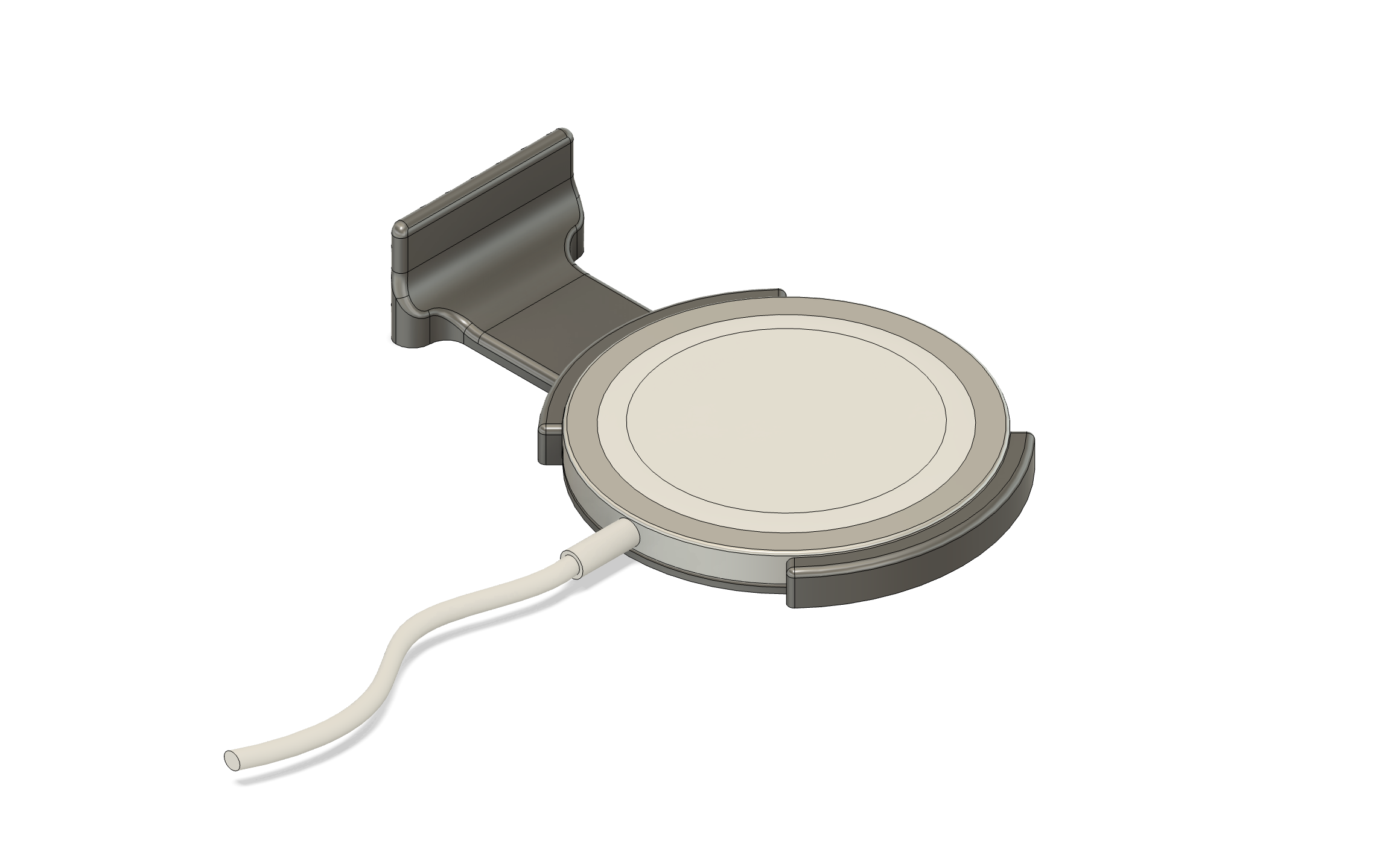
My solution aims to make this action easier by extending and expanding the outer edge of the charging puck, so that your fingers do not have to curl underneath the phone to push against the charger’s body.
Additionally, a curved sliding surface ensures that the phone comes away from the surface and does not reattach itself. The whole motion is quick and easy.
Non-MagSafe Chargers
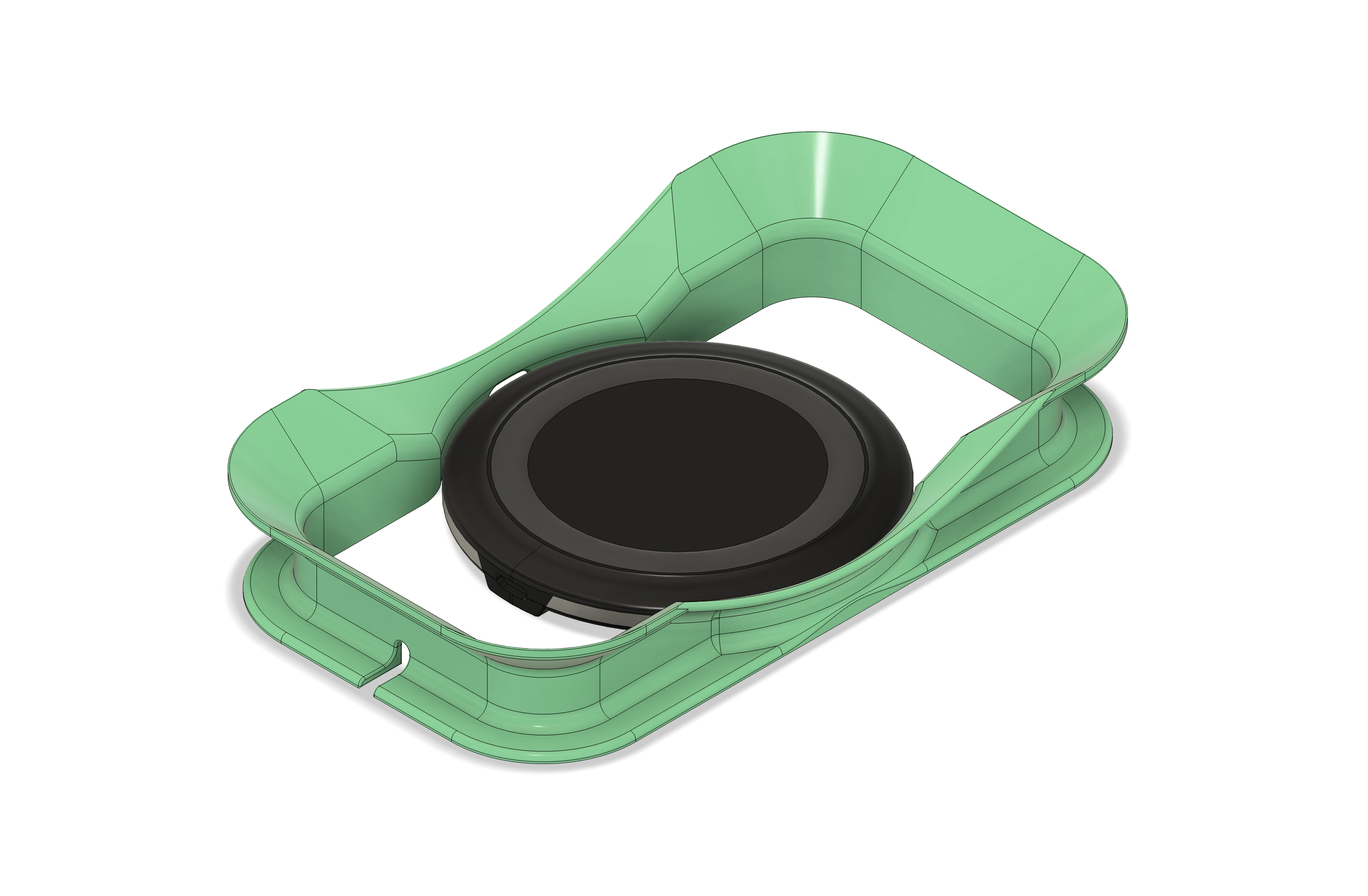
For the non-magnetic chargers the main issue is alignment, so the solution here is a simple guiding frame that helps the user to perfectly center the phone each time it is placed down.
I have explored additional features, like a funnel shape at the top to increase the room for error, but ultimately discovered during testing that it is really not that necessary.
Iterations
MagSafe Charger
I started off by designing a prominent push tab, however underestimated the importance of simultaneously raising the phone away from the magnet.
While it worked great to disengage the magnets, the phone remained on the same plane. When you try to pick up the phone, the magnet simply reattaches itself.
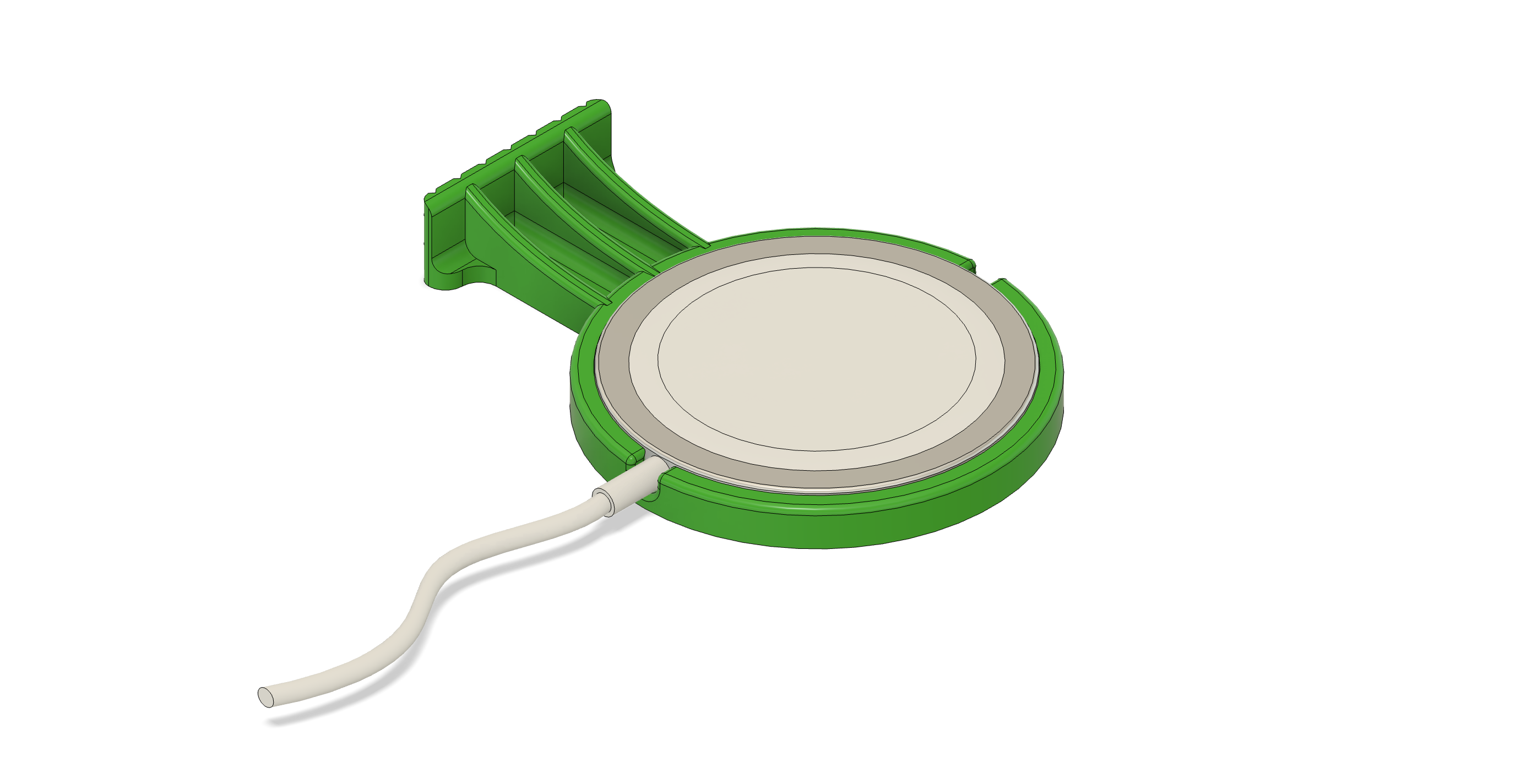
For the second iteration I added a ramp that is made out of 3 ribs (see DFM section below). When the phone is being picked up, these ribs raise the phone's edge away from the surface and ultimately over the top of the push tab.
For a smoother motion, the push tab was made shorter to reduce how much the edge needs to travel before the phone ends up in your hand.
Non-MagSafe Chargers
For my first iteration, I decided to go with an alignment frame that fits around the charging puck. The idea was to create a funnel shape at the top that would help the phone self-align when placed at an angle. Since the charger rests on the ground surface, the silicone ring at its bottom is sufficient to prevent slipping.
One of the main issues with this specific design that I quickly discovered was that my rubberized phone case created a lot of friction with the inside of the funnel and the phone simply did not slide into position as intended. The horizontal print lines did not help and only added to this friction.
In addition, the guiding frame has a rather large footprint, which could be an issue for smaller bed stands.
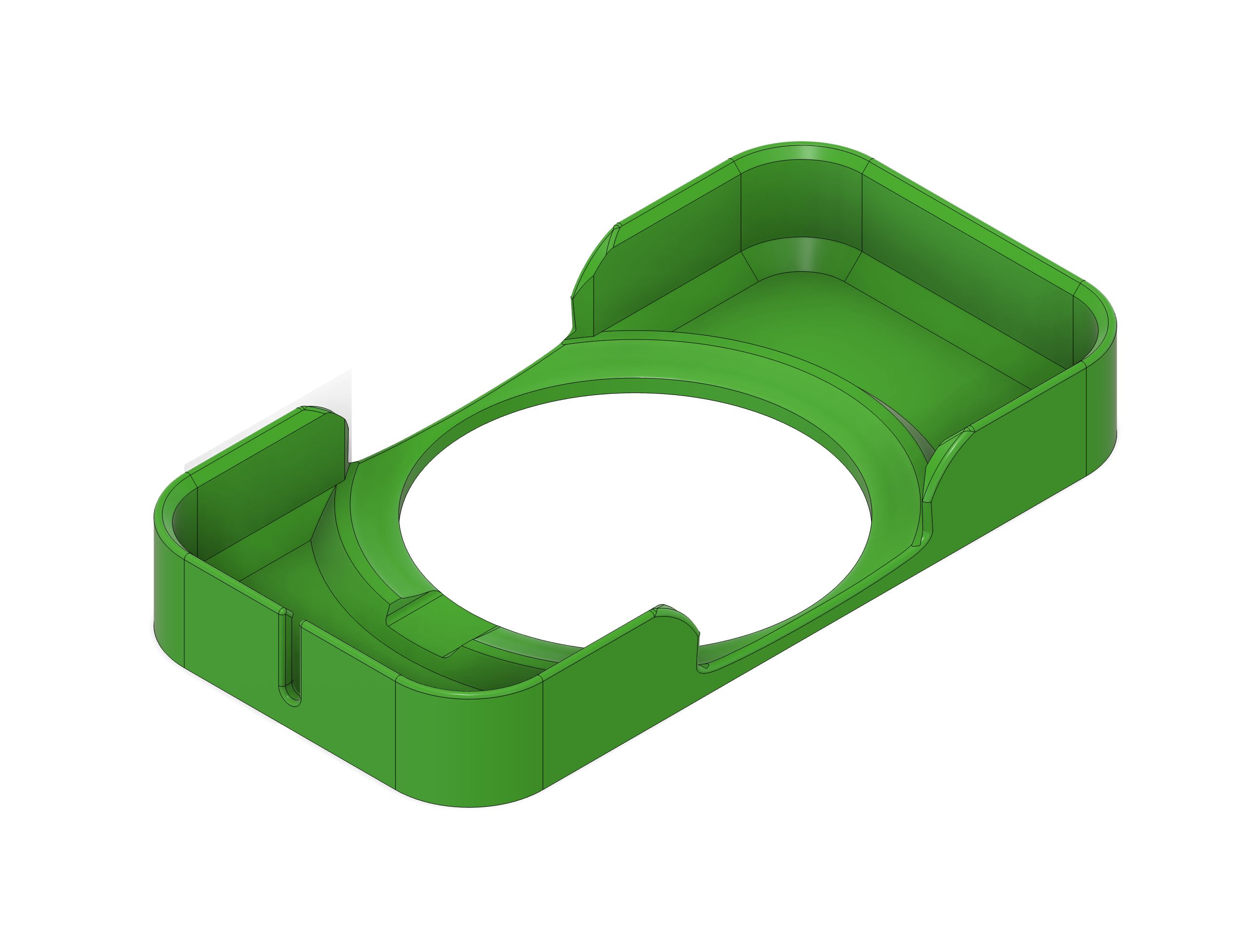
The second iteration is essentially a tray goes underneath the charger, which allows it to be narrower. I found that placing the phone inside a visible frame is already a large usability improvement over the “trial and error” approach of using the puck itself.
DFM considerations
MagSafe: The part has a rather simple geometry and almost uniform thickness throughout. The ejection ramp is made with ribs, rather than a solid surface, which was done to reduce the amount of material used, but also avoid a thick section with lots of infill.
An alternative would be to shell out that area from underneath.
Non-MagSafe: The simple geometries of the second iteration are a clear advantage when considering injection molding. Though that too will require some modifications, like adding draft angles, for instancs.
Since the charger is raised over the surface, the second iteration’s design requires an addition of an anti-slip surface to the bottom of the guiding tray. That extra step is avoided when the frame goes around the charger, like in the first iteration.